Opens in a new tab
Innovative Air Quality Solutions
Xiamen, Fujian, China
Qualified Manufacturing Partner — Air Care Volume Production

Southeast China Air Care Manufacturing Base

High-Volume Assembly, Environmental Validation & Multi-Category Air Care Production

A long-established air care appliance manufacturing partner within the HisoAir network, supporting international brands from tooling qualification through high-volume assembly. Every platform built here passes in-house CADR, acoustic and electrical validation before it reaches a third-party laboratory.
PRIMARY FACILITY ROLE
High-Volume Assembly & Multi-Category Air Care Production
ENGINEERING DEPTH
In-House CADR, Acoustic, EMC & Environmental Chambers
PRODUCTION RESILIENCE
Dual-Site Capacity — China Base + Southeast Asia Secondary Plant
Discuss Manufacturing Program →View Real Factory Evidence
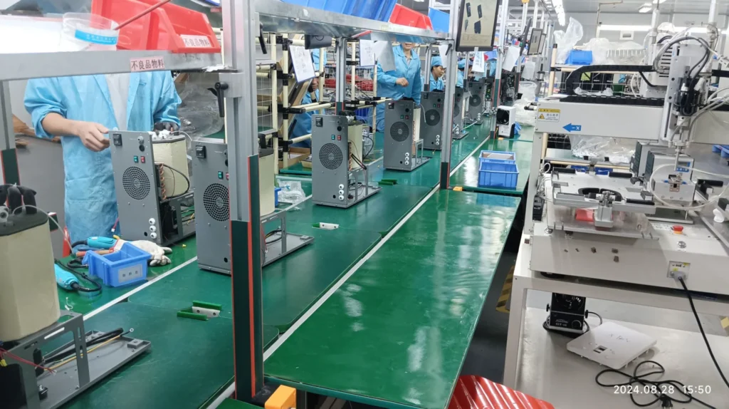
Air care appliance assembly line at HisoAir partner manufacturing facility in Southeast China
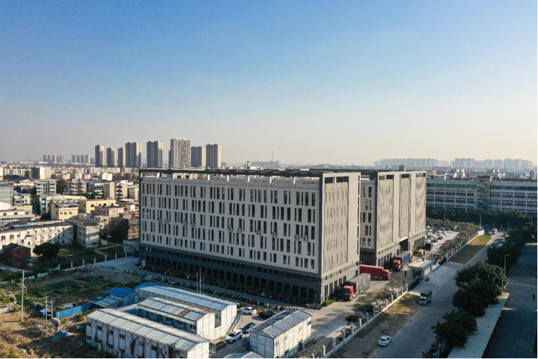
Facility View: Partner air care manufacturing base and environmental validation laboratories, Xiamen, Fujian.
STRATEGIC LOCATION VALUE

Why This Facility

Xiamen anchors one of China's most mature home appliance manufacturing clusters, pairing two decades of category-specific production experience with direct deep-water port access for North American and European shipping lanes.

Role 01

Category-Dedicated Experience

Two decades building air purifiers, humidifiers, dehumidifiers and air circulation products exclusively. Tooling behaviour, assembly sequencing and field failure modes across these categories are known quantities here — not lessons learned on your program.

Role 02

Validated Before It Ships

Nine in-house laboratories cover CADR, acoustics, EMC, airflow and environmental simulation. Performance and compliance risk surfaces during pilot builds rather than during certification submission, when a failure costs months.

Role 03

Volume Without Compromise

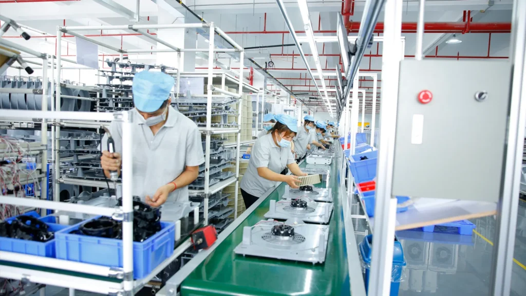
A 30,000 m²-class facility running six assembly lines at 300,000 units-per-month-class capacity, staffed by a 500-person team with a quality function that reports independently of production management.

Role 04

Tariff & Continuity Planning

A secondary production site in Southeast Asia provides an alternative country of origin for programs exposed to tariff volatility or single-country supply disruption.

INTEGRATED ENGINEERING DISCIPLINES

Core Capabilities

This facility's contribution to the HisoAir network is verification depth and assembly scale — the disciplines that determine whether a validated design survives mass production intact.
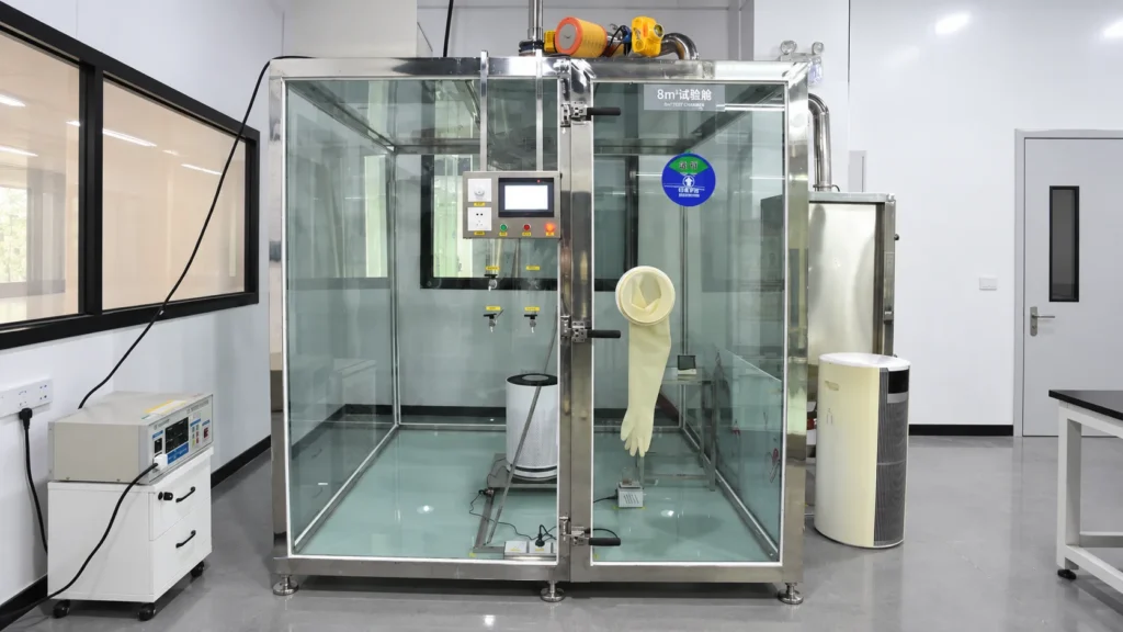
Sealed CADR test chamber for air purifier clean air delivery rate measurementIndustrial Design & Product Definition
Capability 01

Environmental Performance Validation

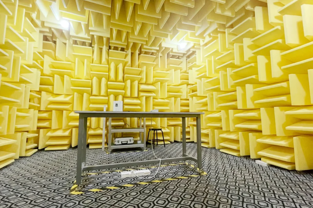
Three-tier CADR test chambers (1 m³, 3 m³ and 30 m³) supporting particulate clean air delivery rate measurement from desktop units through whole-room platforms.
Air purifier sound pressure measurement in an anechoic acoustic laboratoryIndustrial Design & Product Definition
Capability 02

Acoustic Engineering & Noise Validation

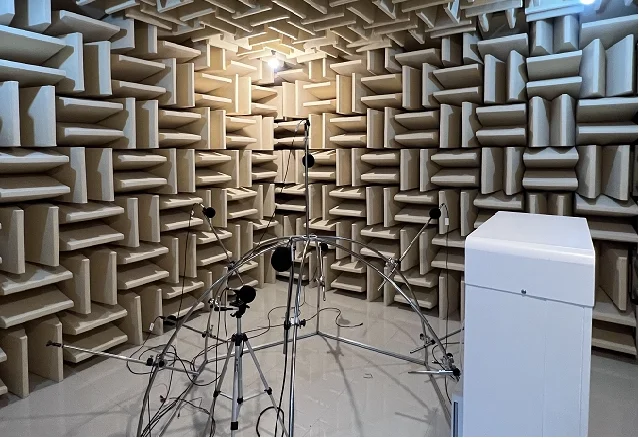
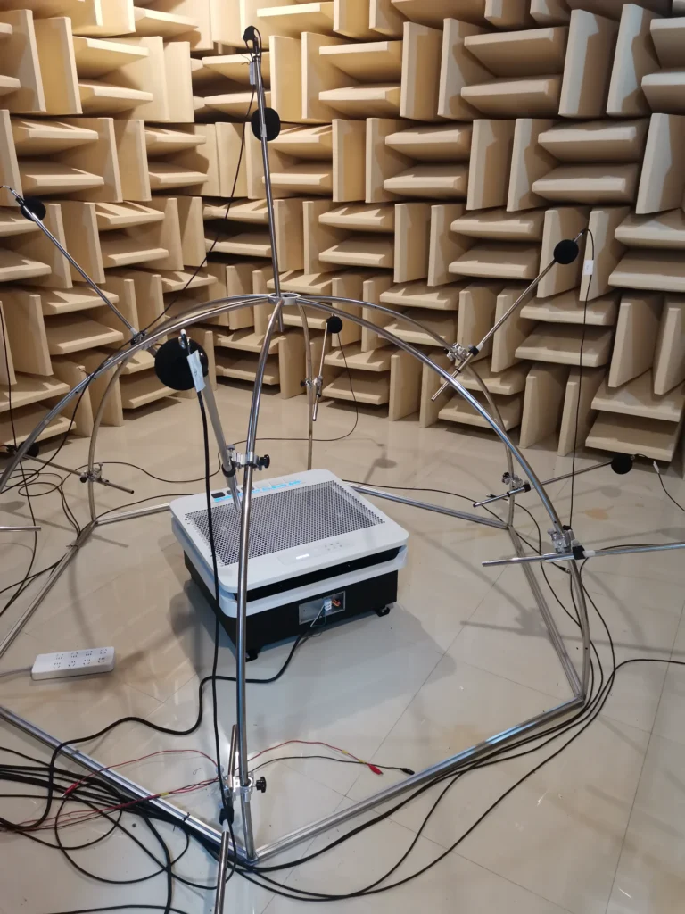
Dedicated acoustic laboratory for sound power and sound pressure measurement, enabling fan curve and baffle geometry optimization against target dB(A) at every speed setting.
Air purifier airflow test rig for static pressure and volumetric flow measurementIndustrial Design & Product Definition
Capability 03

Airflow & Thermal Engineering

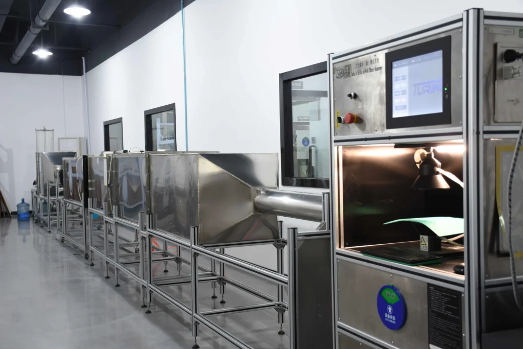
Airflow laboratory for static pressure, volumetric flow and filter loading characterization, plus environmental simulation chambers for temperature and humidity endurance cycling.
Air purifier undergoing EMC pre-compliance emissions testing in an on-site test chamberIndustrial Design & Product Definition
Capability 04

EMC & Electrical Safety

On-site EMC laboratory for pre-compliance emissions and immunity screening, reducing certification failure risk before samples reach accredited third-party laboratories.
Injection mould tooling qualification and T1 sample inspectionIndustrial Design & Product Definition
Capability 05

Tooling & High-Volume Assembly

Injection tooling qualification, T0–T2 sample review, line balancing across six assembly lines, and in-line functional test fixtures at every station.
Quality inspector performing incoming component inspectionIndustrial Design & Product Definition
Capability 06

Quality Systems & Market Compliance

An independent quality function running documented inspection protocols, with production experience against CE, CB, ETL and ISO requirements for EU and North American market entry.

MANUFACTURING VERIFICATION & E-E-A-T

Quality, Verification & E-E-A-T

Empirical verification and transparent supplier governance form the backbone of our manufacturing management.

SITE VERIFICATION DOSSIER
MANUFACTURING RELATIONSHIP
Qualified Manufacturing Partner — Long-Term Production Agreement
AUDITED & VERIFIED BY
HisoAir Supply Chain & Engineering Team
LAST SITE REVIEW
August 2026
QUALITY SYSTEM GOVERNANCE
Facility operates under ISO 9001 quality management systems, with a quality function structurally independent of production management.
DOCUMENTATION ACCESS
Facility audit summaries, capability matrices and product test records available for qualified programs under NDA. Certification documents are held by the manufacturing entity and are model-specific.

Standard Quality Control Process

Unified 6-stage quality assurance protocol deployed across all partner manufacturing facilities.
01
Supplier Qualification
Component audit & vendor quality compliance
02
Incoming Inspection (IQC)
MIL-STD-105E AQL inspection on critical parts
03
Production QC (IPQC)
Process verification, torque logs & line checklists
04
Functional Testing
100% electrical safety, power & sensor checks
05
Final Inspection (FQC)
Finished good audit, cosmetic check & packaging
06
Corrective Action (CAPA)
Closed-loop 8D root-cause corrective reporting
Regulatory Compliance & Laboratory Disclaimer:

Product certifications and test reports are model-specific and may vary by manufacturing location and destination market. Certifications held by partner manufacturing entities are issued to that entity and to specific models; they do not transfer automatically to other products or facilities. HisoAir coordinates testing with accredited third-party laboratories (including UL, ETL, CE, CB, RoHS and CARB) based on specific client programs and country-level regulatory standards.

VERIFIABLE OPERATIONAL PROOF

Real Factory Evidence

On-site operational photographs taken during audit visits, laboratory validation and pilot production batches at this facility.

T1 tooling samples inspected for dimensional accuracy, surface quality, assembly fit and mould cavity condition before design approval.
Proof 01

Tooling & T1 Sample Review

T1 tooling samples inspected for dimensional accuracy, surface quality, assembly fit and mould cavity condition before design approval.—2026-05

Tooling
Xiamen, Fujian, China
Verified Operational Record
Particulate CADR performance validated in a 30 m³ test chamber during engineering and pilot-batch qualification.
Proof 02

CADR Performance Validation

Particulate CADR performance validated in a 30 m³ test chamber during engineering and pilot-batch qualification.—2026-06

Product Validation
Xiamen, Fujian, China
Verified Operational Record
Product noise and acoustic performance measured across operating speeds to verify target performance before production release.
Proof 03

Acoustic Performance Validation

Product noise and acoustic performance measured across operating speeds to verify target performance before production release.—2026-06
Product Validation
Xiamen, Fujian, China
Verified Operational Record
Conducted emissions and preliminary EMC screening performed before formal third-party certification submission.
Proof 04

EMC Pre-Compliance Screening

Conducted emissions and preliminary EMC screening performed before formal third-party certification submission.—2026-01

Compliance Verification
Xiamen, Fujian, China
Verified Operational Record
Pilot-batch assembly used to verify work instructions, assembly sequence, functional test fixtures and critical production checkpoints.
Proof 05

Pilot Run Process Verification

Pilot-batch assembly used to verify work instructions, assembly sequence, functional test fixtures and critical production checkpoints.—2026-09

Pilot Run
Xiamen, Fujian, China
Verified Operational Record
100% end-of-line functional and electrical safety testing performed before final inspection, packing and shipment release.
Proof 06

Mass Production End-of-Line QC

100% end-of-line functional and electrical safety testing performed before final inspection, packing and shipment release.—2026-09

Mass Production QC
Xiamen, Fujian, China
Verified Operational Record
Contaminant Engineering•3 min read

PFAS Water Filtration Technologies Explained: Carbon, Resin & RO

Key Takeaway:

PFAS reduction depends on the specific compounds present, treatment media, contact time, water chemistry, and system design. Activated carbon, ion exchange, and Reverse Osmosis address PFAS through different mechanisms.

PFAS are a large family of persistent fluorinated compounds that can occur in drinking-water supplies. Their treatment behavior varies significantly by molecular structure, chain length, functional group, concentration, and the chemistry of the source water.

Granular Activated Carbon (GAC) removes PFAS primarily through adsorption. It is generally more effective for many longer-chain PFAS, while shorter-chain compounds tend to break through more quickly. Carbon performance depends on media properties, Empty Bed Contact Time (EBCT), competing organic matter, loading, and replacement frequency.

Ion-exchange resins use charged functional sites to capture many PFAS compounds. Properly selected anion-exchange media can provide high capacity and may perform better than conventional activated carbon for some shorter-chain PFAS, although performance still depends on water chemistry and competing ions.

Reverse Osmosis (RO) uses membrane separation rather than adsorption. Properly designed RO systems can provide broad reduction across many PFAS compounds as well as dissolved salts and other contaminants. Unlike carbon or resin, however, RO also produces a concentrate stream that must be managed.

No single technology should be selected from a PFAS label alone. System design should consider which PFAS compounds are present, their concentrations, required reduction targets, flow rate, media life, and the applicable third-party certification or validation requirements.

HisoAir Water Technical Series
Product Discovery•3 min read

How to Choose an Under-Sink Water Purifier for Modern Kitchens

Key Takeaway:

Match the treatment technology to your water quality first, then evaluate cabinet space, faucet configuration, flow rate, drain and power requirements, and filter replacement needs.

Choosing an under-sink water purifier starts with water chemistry. Carbon filtration is well suited to chlorine, taste, odor, and many organic contaminants, while Reverse Osmosis is more appropriate when dissolved salts, fluoride, nitrates, or broader dissolved contaminants need to be reduced.

For compact kitchens, tankless RO systems eliminate the conventional storage tank and can significantly reduce the space required under the sink. However, membrane capacity stated in GPD does not directly equal faucet flow. When comparing systems, check the actual dispensing flow rate, inlet-pressure requirement, recovery ratio, and whether a booster pump is required.

Installation architecture also matters. Many RO systems require a drain connection, electrical power, and either a dedicated drinking-water faucet or a compatible multi-function faucet. High-flow carbon systems can often connect directly to the existing cold-water line with a simpler installation, but pressure drop and available faucet flow should still be verified.

RO also removes much of the naturally occurring dissolved mineral content. Where taste or mineral balance is a priority, a post-RO remineralization stage can be added. Filter life should be evaluated by both rated capacity and local water quality rather than replacement time alone.

The right system is therefore not simply the smallest or highest-GPD model. It is the configuration that matches the target contaminants, available cabinet space, desired faucet setup, peak dispensing demand, and maintenance expectations.

HisoAir Water Technical Series
Water Quality•2 min read

What Does TDS Mean in Drinking Water? Measurement vs Contaminant Reality

Key Takeaway:

A TDS meter estimates the overall concentration of dissolved ionic substances from electrical conductivity. It cannot identify specific contaminants or determine whether water is chemically safe.

Total Dissolved Solids (TDS) refers to the combined concentration of dissolved substances in water. Most handheld TDS meters do not measure TDS directly. Instead, they measure electrical conductivity (EC) and convert that reading into an estimated parts-per-million (ppm) value.

This means a TDS reading can indicate how much dissolved ionic material is present, but not what that material actually is. Calcium, magnesium, sodium, nitrates, and other dissolved ions can all contribute to conductivity, yet a simple TDS meter cannot distinguish between them.

TDS meters are also not suitable for detecting trace contaminants such as PFAS, many VOCs, pesticides, pharmaceuticals, or disinfection byproducts. These substances may be present at concentrations far below the level needed to noticeably change electrical conductivity.

A low TDS reading therefore does not guarantee safe drinking water, and a higher TDS reading does not automatically indicate contamination. Water-treatment decisions should be based on laboratory testing for specific contaminants of concern rather than TDS alone.

HisoAir Water Technical Series
Technology Selection•2 min read

RO vs UF Water Filtration: Understanding Pore Sizes & Dissolved Minerals

Key Takeaway:

Ultrafiltration can reduce bacteria, turbidity, and suspended particles while retaining most naturally occurring dissolved minerals. Reverse Osmosis provides much broader reduction of dissolved salts and smaller contaminants.

Ultrafiltration (UF) typically uses hollow-fiber membranes with pore sizes in the approximate 0.01–0.1 micron range. These membranes physically retain turbidity, suspended solids, colloids, and many microorganisms while allowing dissolved minerals and salts to remain in the water.

Reverse Osmosis (RO) operates at a much finer separation level. Unlike UF, RO can substantially reduce dissolved ions such as sodium, calcium, fluoride, nitrates, and other contributors to total dissolved solids (TDS). This makes RO more suitable when dissolved-salt reduction is a primary treatment objective.

UF generally requires less system pressure and produces little or no continuous concentrate stream in many point-of-use configurations. RO typically requires greater pressure and produces a reject-water stream, but delivers broader contaminant reduction.

For water with acceptable TDS and mineral content, UF can be a simpler mineral-retaining treatment option. Where dissolved salts, fluoride, nitrates, or broader dissolved contaminants are a concern, RO is generally the more appropriate technology.

HisoAir Water Technical Series
Technology Selection•4 min read

Carbon Block vs Reverse Osmosis: Which Fits Your Need?

Key Takeaway:

Choose RO for dissolved inorganic salts and heavy metals; choose Carbon Block for chemical taste/odor, no wastewater, and high line-pressure flow.

Reverse Osmosis (RO) and Carbon Block filtration represent two fundamentally different treatment methods: membrane separation and adsorption. Understanding these differences helps determine which technology is better suited to a specific water-quality requirement.

Reverse Osmosis uses a semi-permeable membrane with pore sizes of approximately 0.0001 microns. It can significantly reduce dissolved inorganic contaminants such as TDS, fluoride, nitrates, and certain heavy metals. Because water must be forced through the membrane, RO systems require sufficient pressure or a booster pump and generate a concentrated wastewater stream.

Carbon Block filtration relies primarily on adsorption through compressed activated carbon, commonly with nominal pore sizes around 0.5–5 microns. It is highly effective for chlorine, chloramines, VOCs, taste, and odor, while allowing substantially higher direct-flow rates without producing wastewater.

From an operating perspective, Carbon Block systems are generally simpler, require less energy, and avoid the water loss associated with RO. RO involves higher system complexity and operating cost, but provides substantially broader reduction of dissolved contaminants that Carbon Block alone cannot address.

HisoAir Water Technical Series

REQUEST A QUOTE